Joy-Con drift repair kit screwdrivers and screws: types, sizes, and handling that prevent damage
Joy-Con screws and screwdrivers determine whether a drift repair avoids stripped fasteners and housing marks. Selecting the correct driver type and size reduces those risks. The repair kit provides tools and spare fasteners that help prevent damage during disassembly.
The 'right tool' is mostly about fit, not force. A driver bit that seats fully inside the screw head transmits torque evenly and reduces cam-out, while a slightly oversized or worn bit can round the recess or slip and scratch the housing. Outcomes vary with screw condition, bit wear, and model tolerances, so checking fit before applying full pressure is essential. The focus is on screwdrivers and screws, not drift diagnosis or full teardown steps.
Types, sizes, and handling that prevent damage start with choosing the correct driver type and confirming fit. Common bit types and sizes include:
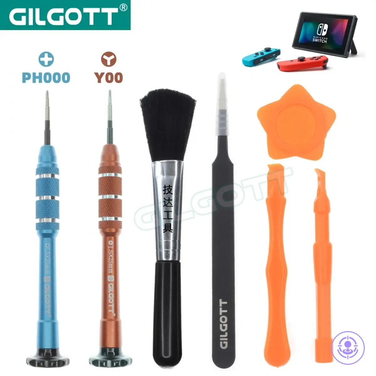
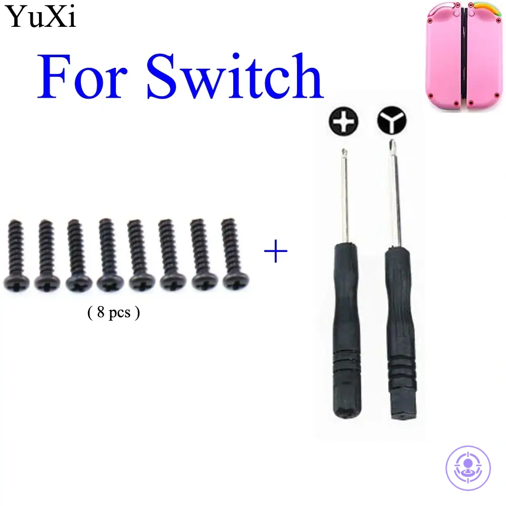
- Tri-wing (Y-type) and small Phillips (cross) bits for the different screw heads found on Joy-Con shells.
- Bit sizes such as Y1.5 and PH000 that match the recess dimensions closely to support full seating.
- Handling that keeps the driver perpendicular and applies steady pressure to reduce cam-out.
- Spare screws included in many kits to replace any that get damaged or lost.
When you have selected driver bits, verify screw types (some models use Y2.0 screws) and check that the bit seats without wobble. Identifying screw types before turning avoids mismatched driver choices. Driver families and fit checks follow.
Fasteners in Joy-Con repairs: what this page covers and what it does not
This page covers specific fastener and driver decisions for Joy-Con drift repair kits. It focuses on choosing the right screws and screwdrivers and handling them properly to avoid stripping threads or damaging the housing—the main risks when handling Joy-Con fasteners.
Loose or stripped screws can cause Joy-Con instability and worsen drift symptoms. Some repair attempts fail due to wrong driver size or poor technique that damages mounting points. A ‘fit first’ approach—matching driver to screw head and applying controlled torque before disassembly—reduces damage and makes the repair safer.
To avoid scope confusion, note that this page covers only fastener and driver decisions; it does not cover full repair steps.
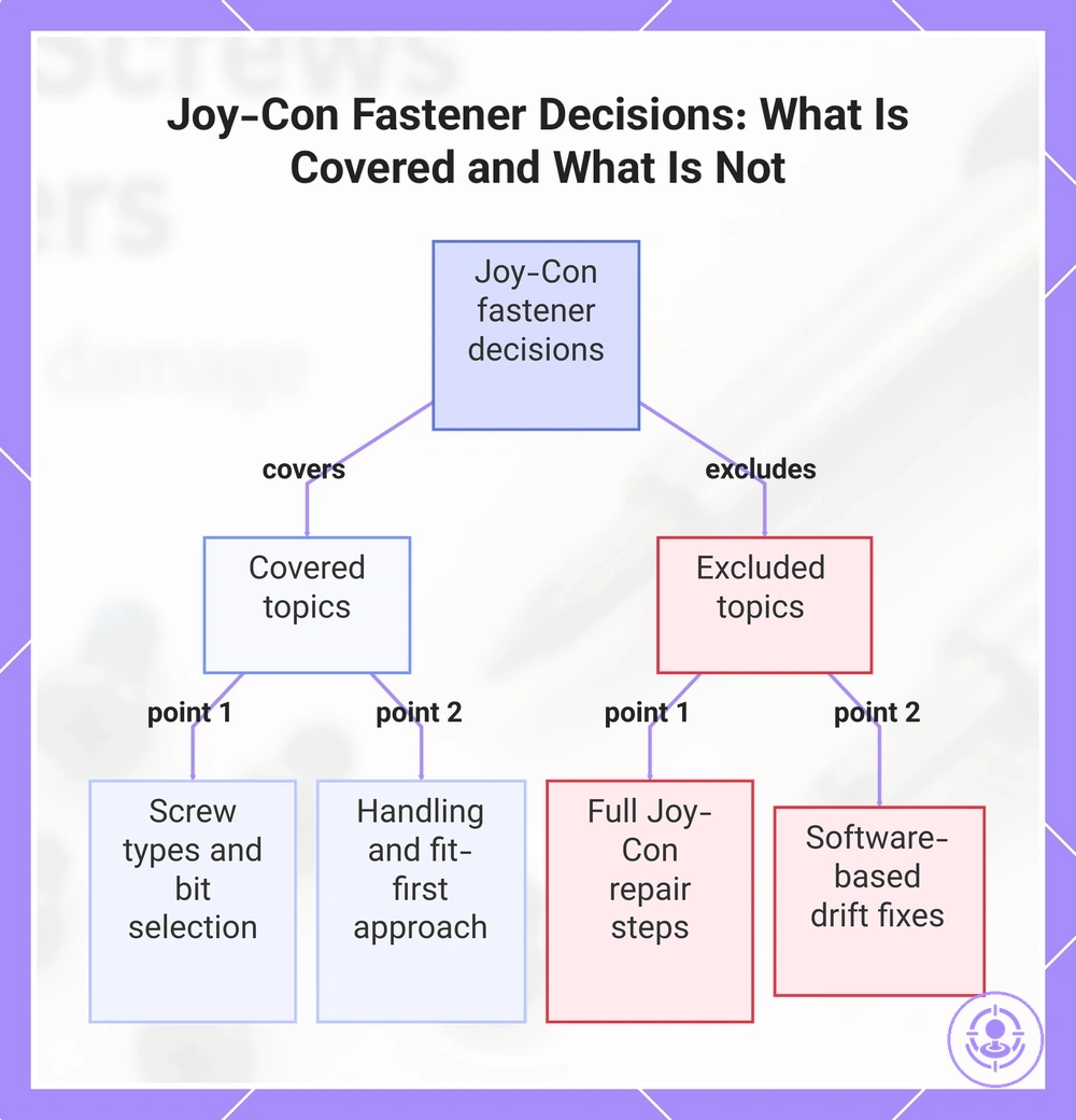
- Covers: Identifying common screw types and sizes used in Joy-Con rail assemblies.
- Covers: Selecting compatible screwdrivers such as Tri-point Y00 and Phillips #00 bits.
- Covers: Careful handling techniques to reduce stripping and housing marks during screw removal and reinstallation.
- Does not cover: Full analog stick replacement or drift calibration steps.
- Does not cover: Disassembly of the Switch console body or other components beyond the Joy-Con fasteners.
- Does not cover: Software-based drift fixes or calibration tutorials.
A common assumption is that any small screwdriver works—but that can strip heads or damage threads; fit and handling matter more than brand. This page limits its scope to fastener and driver decisions because those choices affect repair safety and outcome. Once the scope is clear, the prep checklist before you start covers the tools and workspace setup needed for fastener-related work.
This chart shows the scope of fastener and driver decisions covered in this repair guide, including the key topics addressed and the areas explicitly excluded.
Screwdriver Types Required for Joy-Con and Switch Hardware Screws
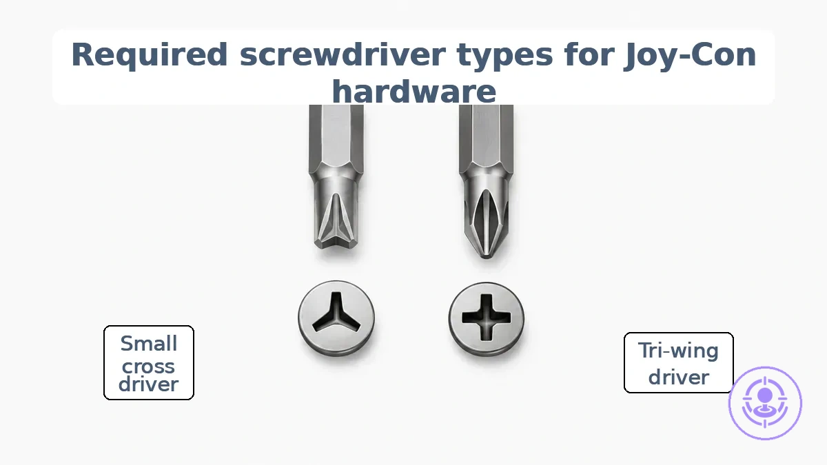
Two main screwdriver types are typically needed for Joy-Con and Switch hardware screws: a tri-wing (tri-point) driver and a small cross (Phillips-style) driver. Each corresponds to a specific screw head shape used on the controller and console. The correct driver family matters: match the head, not the label.
These two driver types exist because Nintendo uses different screw head geometries for different purposes. The tri-wing heads resist cam-out and are used on exterior panels, while small cross heads appear on internal brackets and components. When the wrong driver type is used, the bit may fail to seat properly, increasing the risk of slip and stripping. The fit between screw head and driver type is the first layer of damage prevention.
Screwdriver types required for Joy-Con hardware: tri-wing and small cross bits matched to their screw head shapes.
The table maps driver types to screw head types and fit risks.
| Screw head type | Driver type | Fit risk if mismatched |
|---|---|---|
| Tri-wing (Y-shaped) | Tri-point / tri-wing | Bit slips; screw head may round out |
| Small cross (plus-shaped) | Phillips-style | Bit wobbles; recess strips easily |
The tri-wing driver fits the three-slotted Y-shaped screw heads found on the outer shell of the Joy-Con and the Switch back panel. The small cross driver fits the common plus-shaped recess used inside the controller, such as on the bracket that holds the analog stick module. Depending on the specific model or revision, screw placement and size may vary, so check the head before selecting the driver.
A common assumption is that a single precision screwdriver can handle both screw types, but the tip profiles are incompatible. The tri-wing recess may not properly accept a cross bit, and forcing a tri-wing bit into a cross recess can strip the head. Before applying torque, verify seating: the bit should sit fully without rocking.
Tri-wing drivers: fit, tip geometry, and why near-matches cause damage
A properly fitting tri-wing bit matches the wing depth and tip sharpness precisely enough to eliminate wobble. When fully seated, the bit engages all three wings without rocking and transfers torque evenly.
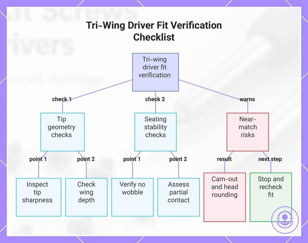
The following checklist verifies fit, tip geometry, and near-match risk to reduce cam-out and head rounding:
- Inspect tip sharpness: Dull or chipped edges reduce bite and increase slip risk.
- Check wing depth: The bit should reach the bottom of each slot for full contact.
- Verify seating stability: Insert the bit and rock it side to side—any play signals a size mismatch.
- Assess risk of partial contact: If only two wings engage, torque can concentrate and rounding may occur.
- Watch for worn bits: A bit that once fit may now slip after repeated use.
A tri-wing bit that does not seat fully makes cam-out likely. The driver can slip out under load, rounding the head and making removal harder. Near-matches that look correct but lack the exact wing profile cause this failure more often. Stop immediately and recheck your fit if the bit feels loose or the screw head starts to deform.
This chart shows the key checks to ensure a tri-wing driver fits properly and warns about near-match risks that cause damage.
Small cross drivers: size standards, tolerance, and common mismatch patterns
Correct small cross driver fit depends on head engagement and tolerance rather than the printed size label; fit matters more than the label for avoiding damage to Joy-Con fasteners. A driver marked as the same size often varies slightly in tip geometry, leading to differences in seating depth and wobble under load.
Common mismatch patterns that signal wrong sizing before damage occurs include:
- Bit rocks side to side after insertion — a sign of excessive clearance or loose tolerance, increasing stripping risk.
- Bit fails to seat fully into the cross recess, leaving a visible gap between tip and screw walls.
- Low-pressure slip before the screw turns indicates insufficient contact or wrong size.
- Driver tip contacts the screw head walls before reaching the bottom, preventing full engagement.
- Bit feels loose even when pressed firmly, often due to a size standard mismatch or worn tip.
Forcing a loose driver can round the recess and make removal harder. Remove the driver, check alignment, and ensure full seating before applying steady torque. If resistance feels off, stop and reseat before turning — that step often prevents stripping and can help preserve the fastener for future disassembly.
Screwdriver Sizing and Quality Checks Before You Turn a Screw
Checking sizing and quality before turning a screw helps avoid stripping by verifying seating and tool condition before applying torque. These fit and tool condition checks verify proper seating and bit condition, so you can proceed or stop before damage occurs.
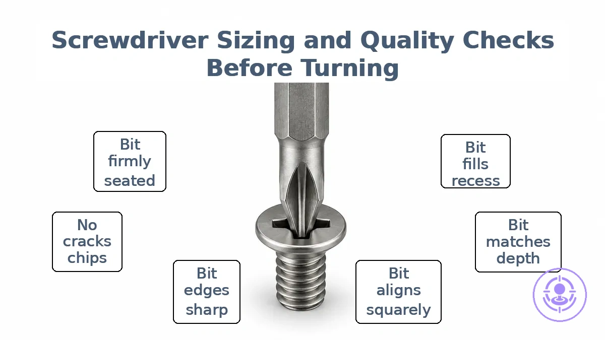
- Fit checks:
- Bit fills the screw recess completely — no side-to-side movement.
- Bit tip matches the head depth — not protruding nor shallow.
- Bit aligns squarely with the screw axis — no tilt or wobble.
- Tool condition checks:
- Bit edges are sharp, not rounded or worn.
- No cracks or chips on the bit tip.
- Shaft and handle are intact, with no loose parts.
- Bit is firmly seated in the driver — no slip in the chuck.
- If any check fails, stop, reassess, and change bit before applying force.
Wobble or a clicking sound when turning often signals poor seating or worn bit edges. Cam-out is more likely when the bit cannot grip fully. If the bit is rounded or the screw recess is deformed, stop, inspect both, reassess, and switch to a fresh bit or a larger size if possible.
Minor tip rounding is often assumed harmless, but even slight wear increases stripping risk, especially with soft screw materials or tight fasteners. Proper sizing and quality checks apply across most screw conditions, but results vary with wear, material, and user pressure. For more on frequent errors, see common mistakes that cause damage after the checklist.
Bit Seating, Cam-out Signals, and Torque Control for Tiny Fasteners
Cam-out happens when a screwdriver bit lifts out of the screw head recess under torque, increasing the risk of stripping the fastener. This slip happens when the rotational force overcomes the frictional grip between the bit and the recess walls. In tiny fasteners like Joy-Con screws, even a brief lift can deform the shallow recess and create casing marks. The main signal is a sudden upward movement of the bit during tightening.
Torque control for tiny fasteners means knowing when to stop rather than hitting a specific numerical value. The right move is to stop turning at the first sign of resistance, reseat the bit, then continue. That pause reduces the chance of rounding the recess or damaging the surrounding plastic.
To avoid sudden slips and casing marks, follow these guidelines:
- Do make sure the bit is fully seated before applying torque.
- Do lift the driver away if you feel the bit begin to slip or wobble.
- Do check the bit tip for wear after repeated use on tiny fasteners.
- Don’t increase downward pressure to force a slipping bit back in place.
- Don’t ignore the click or slip sound—it often signals cam-out has started.
- Don’t continue turning if the screw resists beyond expected friction.
Magnetization and Retention Control for Small Screws
Magnetic retention helps reduce the risk of drops and misplacement when handling small screws during Joy-Con reassembly by holding the screw securely without extra finger pressure. However, magnetization is not always suitable—near sensitive electronics, a demagnetized or non-magnetic driver helps avoid potential interference. These habits focus on retention control for small screws. The goal is to control the screw, not the force.
- Use a magnetized driver tip for ferrous screws.
- Demagnetize the driver before reassembling near Joy-Con circuit boards to reduce magnetic fields near components.
- Keep screws organized in a tray by size to reduce misplacement.
- When starting a screw, apply light pressure and let the magnetic tip hold the screw steady, then drive straight.
- For non-magnetic screws or when magnetization is not possible, use a piece of tape or a rubber finger to hold the screw in place.
- After each screw is started, pause to confirm it is seated straight before tightening.
When magnetization is not available or advisable, alternative retention can help. The key is to avoid forcing the screw before it is aligned—this often leads to cross-threading or a lost screw. A simple habit—placing the next screw on the tray before driving the current one—keeps your workspace organized and lowers misplacement risk.
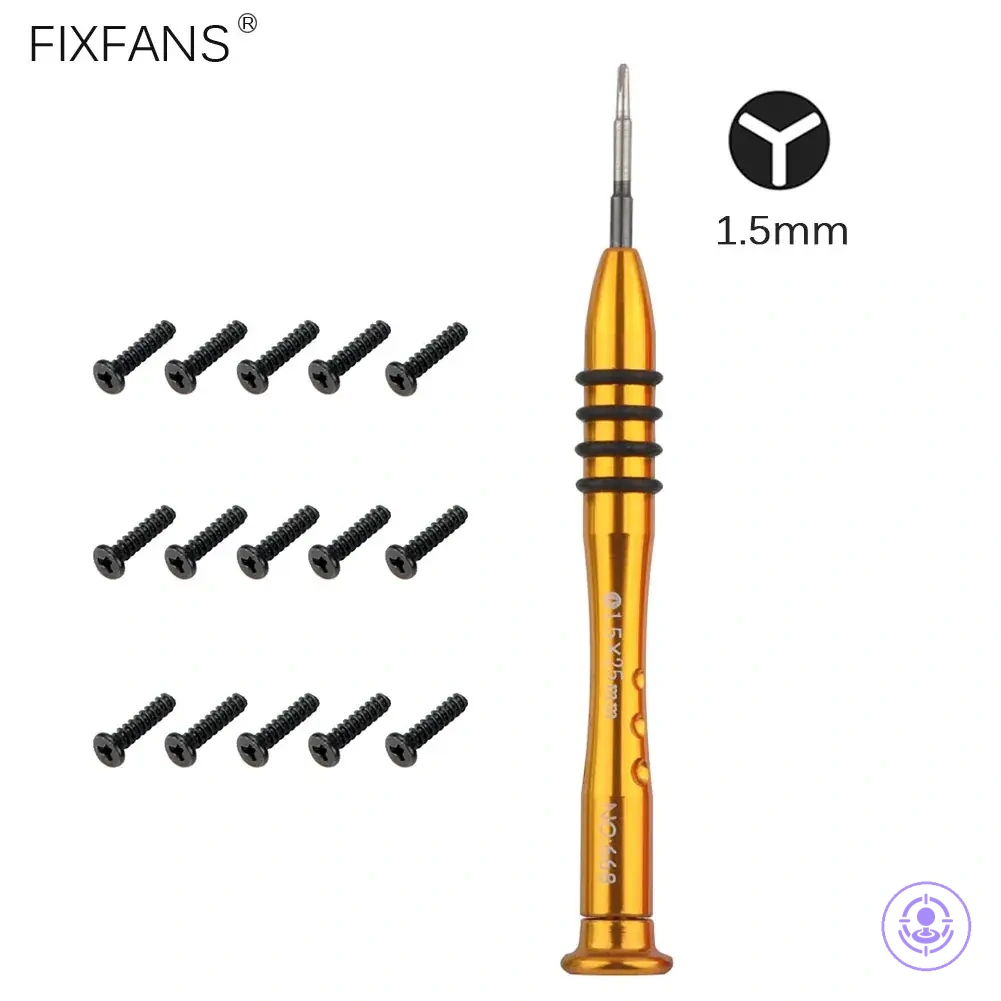
Joy-Con screw types and size characteristics you may encounter in kits
Joy-Con repairs involve multiple screw types where small differences in length or head profile affect fit and safe placement. Kits often include several fasteners that look similar, so matching by observable cues — length, head profile, and thread — is needed.
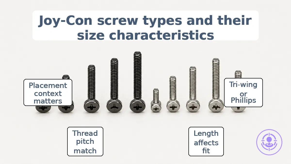
Joy-Con screws typically use a tri‑wing (Y‑type) or Phillips #00 head profile, and the driver fit depends on matching that shape exactly. A visibly longer or shorter screw affects where it can go — placing one that is too long can push through the housing or stress internal components, while too short a screw may not engage the threads properly. Cross‑threading becomes more likely when the thread pitch does not match, leading to stripped or damaged mounting points. The table groups screw types and size characteristics you may encounter in kits, organizing observable cues for safer matching.
| Observable cue | What to check | What it affects | Risk if mismatched |
|---|---|---|---|
| Head profile | Tri‑wing vs. Phillips shape; depth of the recess | Driver fit and torque transfer | Cam‑out or stripping the screw head |
| Length | Overall shaft length from under head to tip | Clearance inside the shell and depth of engagement | Protrusion through the housing (damage) or insufficient grip |
| Thread | Thread pitch and diameter (coarse vs. fine) | Whether the screw bites into the intended threaded boss | Cross‑threading, stripped threads, or loose hold |
| Placement context | Which location (rail, battery bracket, small holes near buttons) | Which screw belongs where; typical length and profile per location | Wrong screw forces itself into a spot not designed for its size |
In a kit with several unmarked screws, compare them side by side. Group them by length first — even a 1 mm difference can indicate a different location.
Check head profile under good light, and separate fasteners where the thread pitch looks different (coarser or finer). Label each group with the intended shell area (e.g., “back shell long,” “rail short”) to prevent mix‑ups during reassembly.
A common misconception is that all Joy‑Cons use exactly the same set of screws. In reality, screw sizes and head types vary between left and right controllers, between the console body and the Joy‑Cons, and even between production batches. Kits reflect this variation, so treating screws as interchangeable without checking their observable cues often leads to stripped heads, cross‑threading, or housing stress. Rely on length and head profile comparisons rather than assuming any screw fits any hole, and use these same cues when selecting replacements.
Identifying the correct replacement screw: thread, length, and head profile cues
Correct replacement depends on matching thread, diameter, length, and head profile rather than using a near-size guess. A screw that looks close but differs in thread pitch or head shape can cause cross-threading, strip the housing, or fail to seat properly. Match thread first.
Verify thread, length, and head profile cues with this checklist to avoid cross-threading and housing stress.
- Check that the thread pitch and diameter match the original screw and the threaded hole.
- Confirm the length provides enough clearance so the screw does not bottom out or protrude.
- Verify the head profile matches the original shape and fits the countersink or recess.
- Confirm the drive recess matches the original screw head for proper tool engagement.
- Inspect the replacement screw's head profile for burrs or damage that could prevent proper seating.
- If the original screw is damaged, use its intact threads and head shape as the reference, not the damaged portion.
If the replacement screw binds or feels tight before fully seated, stop and reassess. A mismatch in thread, diameter, or length can stress the housing threads or crack the plastic. Back it out, recheck the cues, and confirm the replacement matches the original profile before proceeding.
Screw material and finish: stripping risk, brittleness, and longevity signals
Screw material and finish are the composition and surface treatment of the fastener, both affecting head durability and stripping risk under the limited torque of small drivers. Hardness influences how easily the screw head deforms when engaged by a driver. Coatings can reduce friction and wear, but may also alter the torque-tension relationship. The result is a trade-off, not a guarantee of performance.
Hardness mismatch and coating behavior together determine whether stripping appears as head deformation or thread failure. These outcomes depend on the specific application and materials involved.
To see how material and finish choices affect stripping risk and longevity, consider these contrasts:
- A harder screw with a lubricious coating can reduce head deformation but may increase the chance of thread stripping in a softer mating part.
- A softer screw in a hard mating material may cause the screw head to round out sooner, yet it can protect the internal threads from damage.
- A finish that reduces friction can extend the service life of the drive recess by minimizing wear, though it may require torque adjustment to avoid over-tightening.
- A brittle material such as hardened steel can resist deformation but may crack if the driver is misaligned or if torque is applied too quickly.
These contrasts show no single material or finish is universally superior; the right choice depends on the specific assembly conditions.
Avoiding stripped screws and housing damage during disassembly
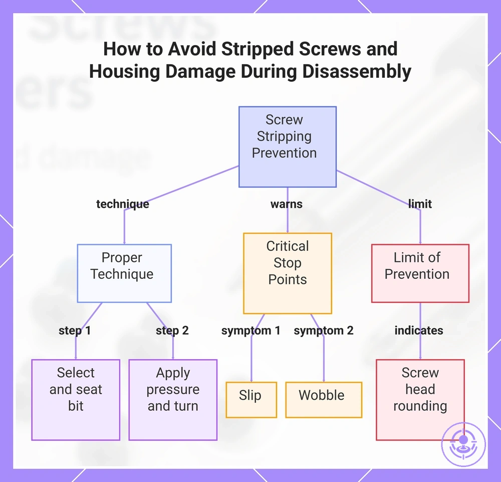
Stripping is most often prevented by correct bit fit, stable seating, and controlled torque rather than added force. When the bit matches the screw head closely and seats fully, the turning force transfers evenly. Any wobble or slip signals poor contact, and continuing under pressure can round the head. In disassembly, force is the enemy.
This safety sequence helps reduce the chance of stripping and housing damage during disassembly.
- Select a bit that fills the screw head without play.
- Insert the bit fully and confirm it does not rock.
- Align the driver perpendicular to the screw axis.
- Apply steady, moderate pressure while turning slowly.
- Stop immediately if the bit slips or the screw wobbles.
- Reassess the fit and seating before resuming.
Slip and wobble are the two critical stop points. Slip occurs when the bit loses contact with the screw head, often due to a bit that is too small or uneven pressure. Wobble indicates the screw is not aligned with the driver, which can damage both the head and the surrounding housing.
If the screw head shows signs of rounding despite correct technique, the prevention sequence has reached its limit. At that point, prevention gives way to containment.
This chart shows the prevention sequence, critical stop points, and containment limit for safe screw disassembly.
When a screw starts to strip: containment steps before removal becomes difficult
When a screw starts to strip, the immediate goal is to contain the damage and restore grip without destructive methods. The early symptom of a screwdriver slipping or biting less indicates that the head grooves are beginning to round.
The steps below preserve removal chances without worsening the head, focusing on re-engaging the driver and preventing further slip.
- Stop turning as soon as you feel the driver slip or cam-out. Continuing to apply force at this point accelerates rounding and worsens containment.
- Re-seat the bit by pressing it firmly into the screw head. Ensure it fully engages the remaining grooves before applying torque.
- Stabilize the driver and screw head by aligning perpendicular to the head. Apply steady downward pressure to maintain contact.
- Check the bit condition. A worn or undersized bit reduces bite and increases slip. Replace it with a sharp, correctly sized bit to improve grip.
- After re-seating and stabilizing, attempt a slow, steady turn. If the bit holds and the screw turns, grip has been restored. If it slips again, stop immediately.
After these containment steps, the likelihood of regained grip depends on how early the slip was caught and how well the driver was re-engaged. If the head deforms more during these actions, stop and move to already-stripped options. These steps can reduce escalation risk but do not guarantee full recovery.
If the screw is already stripped: recovery options that stay within repair-kit scope
When a screw is already stripped, prioritize non-destructive grip-restoration recovery options to avoid irreversible moves that could worsen the damage or break the screw.
The following decision list separates recovery options by severity, each staying within typical repair-kit scope and including a stop condition to indicate when further attempts risk more damage.
- Screw head is slightly rounded, but a bit can still catch: Use a high-quality hardened steel bit of the exact size. Tap the driver handle with a plastic hammer to seat the bit fully. Apply a grip enhancer such as powdered rosin or a rubber band over the head to increase friction. Apply steady, straight torque. Stop if the bit slips again; further attempts may round the head further.
- Screw head is moderately stripped and a standard bit no longer fits: Try a Torx bit that is slightly larger than the original hex or Phillips pocket. Drive the Torx bit into the screw head with light hammer taps to create new engagement splines. This can provide enough grip for removal, but the bit may be damaged. Stop if the screw does not move after two attempts; forcing risks snapping the screw.
- Screw head is fully rounded and the screw is partially protruding: Use a pair of quality screw-extracting pliers to clamp the outer rim of the head. Apply steady, parallel pressure while turning. This works best when the head has enough height to grip. Stop if the pliers slip or the head begins to deform; further force may break the screw.
- Screw head is completely flush or recessed and rounded, with no remaining purchase: No non-destructive method within a basic kit is likely to remove it reliably. Attempting further torque or hammering may damage the surrounding plastic or strip the threaded hole. Stop immediately. The screw has reached the escalation point.
- Screw is seized due to thread-locking residue or corrosion: Apply focused heat using a soldering iron tip to the screw head for 30–60 seconds to soften adhesive or expand the metal. Then attempt removal with a properly seated bit. Stop if the screw does not turn after heating and one gentle attempt; repeated heating may damage adjacent components.
Myth: Sufficient torque can always remove a stripped screw. Truth: For a fully stripped screw in a plastic housing like a Joy‑Con, forcing extraction can crack the shell, strip internal threads, or make the mounting point unusable. These non-destructive grip-restoration options have limits; once they fail, the safe course is to consider professional help or a replacement path.
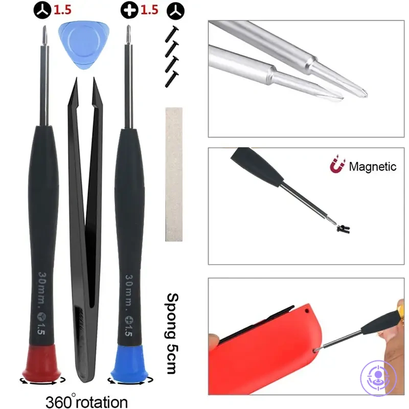
Tools needed beyond screwdrivers: what is essential versus optional for safe handling
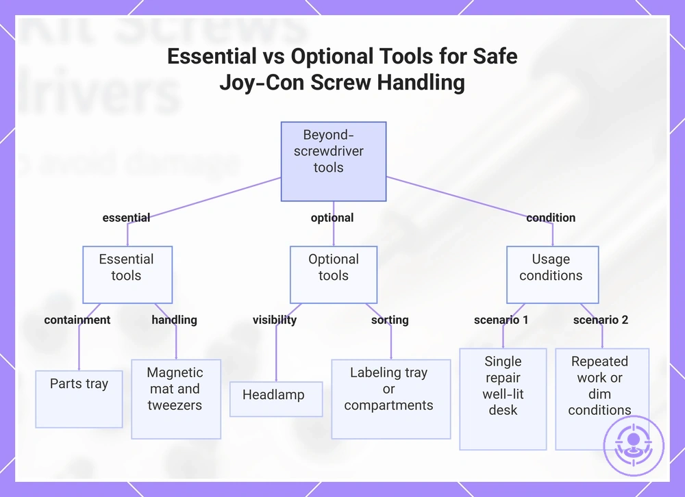
A parts tray, a magnetic mat, and tweezers are the tools beyond screwdrivers that most directly reduce the risk of fastener loss, slippage, and misplacement during Joy-Con screw handling. For most home repairs, the essential small set is enough. This checklist separates essential from optional tools for safe handling, focusing on risk reduction rather than full repair coverage.
Essential
- Parts tray: Reduces the risk of losing small screws by keeping them contained during handling.
- Magnetic mat: Prevents screw slippage and misplacement by holding ferrous fasteners securely.
- Tweezers: Reduce the chance of dropping or misplacing a screw when placing or removing it.
Optional
- Headlamp: Improves visibility in low-light areas, reducing misplacement of small parts.
- Labeling tray: Helps avoid confusion and loss by keeping screws sorted by location.
- Small container with compartments: Keeps screws separated to prevent misplacement and loss.
A parts tray and tweezers directly address the handling risks of loss and misplacement. The tray keeps screws from rolling away, and tweezers provide a stable grip for precise placement. For a broader inventory, refer to the complete kit parts checklist. Do not feel compelled to buy every tool; a focused set is enough.
If you are repairing a single Joy-Con on a well-lit desk, a tray and tweezers may be sufficient. When working repeatedly or in dimmer conditions, a headlamp becomes a practical support tool to keep screws visible. Regardless of the tools you choose, use a small container or labeled tray to keep screws sorted and prevent loss.
This chart separates essential and optional tools for safe handling of Joy-Con screws, focusing on risk reduction.
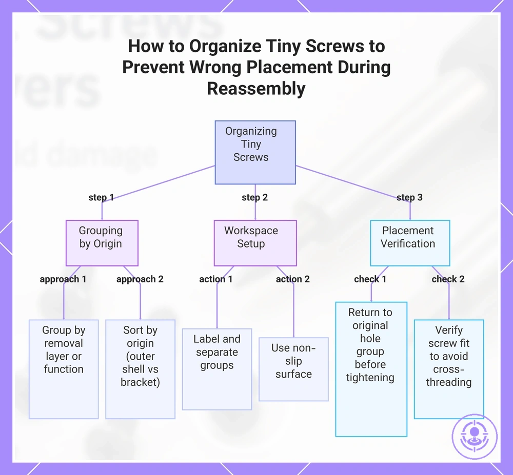
Organizing Tiny Screws to Prevent Wrong Placement During Reassembly
Organizing tiny screws by size and function helps prevent wrong placement and reduces cross-threading risk during reassembly. When a screw of the wrong length is forced into a threaded hole, it can strip the threads or damage the component.
Use this checklist to organize tiny screws into labeled groups and avoid wrong placement during reassembly:
- Group screws by their removal layer or component function.
- Label each group on a tray or paper diagram with a marker.
- Keep screws from different groups separated to prevent mixing.
- Return each screw to its original hole group before final tightening.
- Use a magnetic or non‑slip surface to prevent screws from rolling away.
- Mark screw locations on a simple outline if the assembly is complex.
During Joy‑Con disassembly, sort screws into groups by origin (e.g., outer shell vs. internal bracket) and label each group on a tray. Verify each screw fits its hole before tightening to avoid cross‑threading.
Many people think they can remember screw positions without labeling, but one misplaced screw can cause cross‑threading or damage the threaded hole. For a complete breakdown of tools and steps, see the Joy-Con drift repair kit hub.
This chart shows the key steps to organize tiny screws during reassembly, covering grouping by origin, workspace setup, and placement verification.
Screw trays and labeling habits that reduce loss and cross-threading risk
Using a tray with labeled sections keeps each screw size separate, preventing misplacement and reducing cross-threading risk. The following checklist covers tray and labeling habits that reduce loss and misplacement. Label before you move on.
- Use a tray with multiple compartments to separate screws by size and type.
- Label each section with the screw size (or a matching tag) to avoid confusion.
- Clean compartments before placing new screws to reduce the risk of debris hiding small fasteners.
- Return each screw to its labeled section immediately after removal to maintain order.
- Avoid mixing screws that look similar but have different thread pitches, as this increases cross-threading risk.
- Place the tray in a stable, well-lit area so you can see labels clearly and align screws correctly.
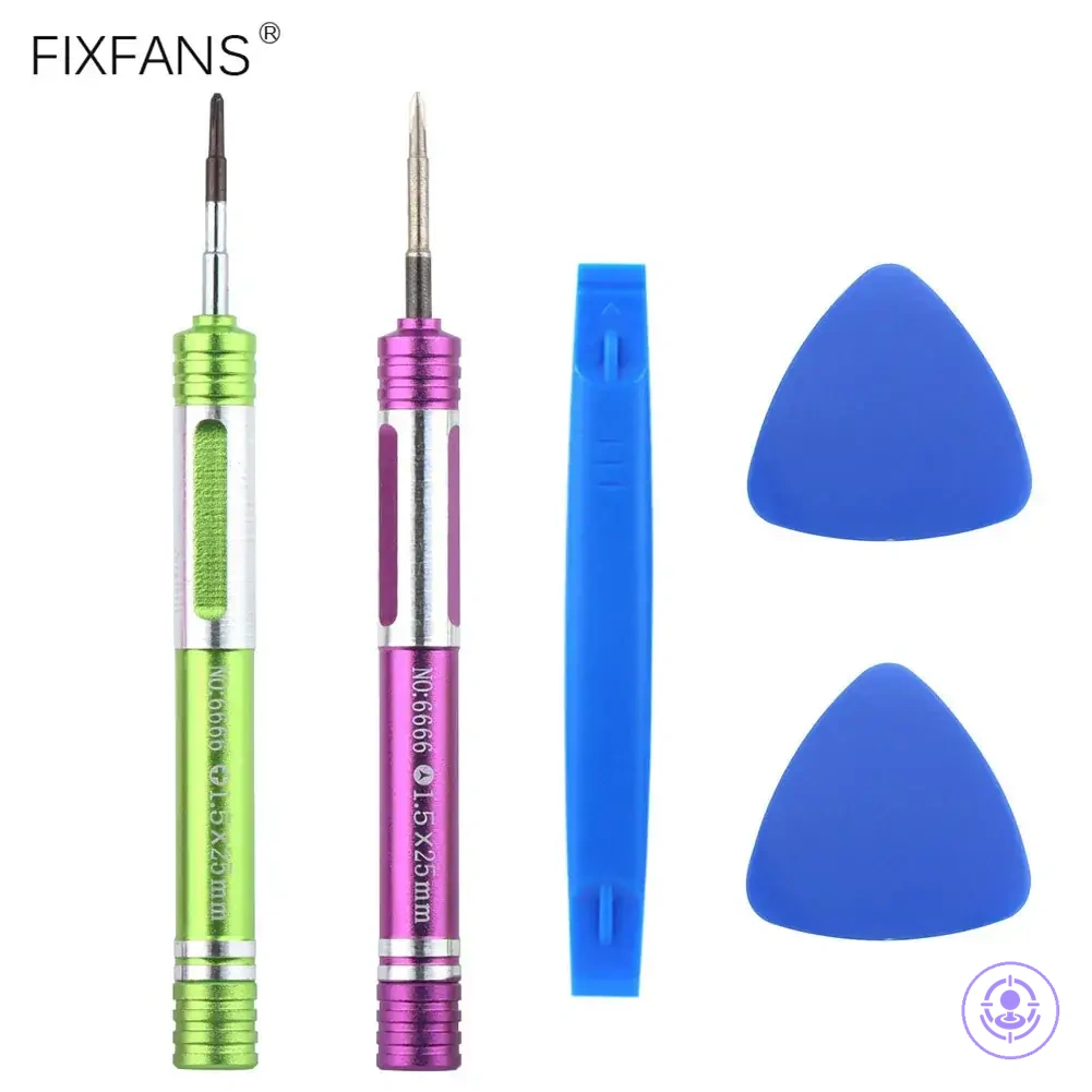
Choosing a repair kit for screwdriver and screw completeness without overbuying
To avoid overbuying, choose the smallest set that still covers the driver types, fit quality, and screw-matching needs for your specific repairs. Doing so helps avoid missing bits and paying for tools you rarely use. The minimum that fits is enough.
Repair kit completeness means having the right driver types and sizes for your actual screws, not the highest bit count. A criteria checklist helps you define completeness without overbuying by focusing on actual needs:
- Identify the screw types (Phillips, flathead, Torx, Pentalobe, and others) you commonly encounter.
- Ensure bits are precision-ground for a snug fit that improves screw matching and reduces the risk of cam-out and stripping.
- Confirm the set includes the required driver sizes (for example, PH0, PH00, T5, T6) for your devices.
- Choose bits made from hardened steel, such as chromium-vanadium, to resist wear.
- Look for ergonomic handles that reduce fatigue during repetitive use.
- Prefer kits with a magnetic tip to hold tiny screws securely during placement.
- Verify the case organizes bits clearly so you help avoid losing small pieces.
- Avoid sets that include excessive specialty bits you rarely need for your current repairs.
The comparison clarifies when each set is appropriate.
| Minimum set includes | Expanded set adds | When it helps |
|---|---|---|
| Core driver types (Phillips, flathead, Torx) | Additional security bits (Pentalobe, Y-tip) | When your repairs include smartphones or game consoles |
| Bits for common electronics (PH0, PH1, T5, T6) | Bits for laptops, power tools, or appliances | When your repair scope expands beyond mobile devices |
| A simple handle with rotating cap | A handle with ratcheting mechanism | When you need faster bit changes or work on larger assemblies |
| Basic storage case | A case with labeled slots and bit holder | When you frequently transport the kit |
Criteria-based selection prevents overbuying without compromising fit.
Here are product examples that may make comparison easier. Before buying, always review the compatibility criteria, essential features, and product details.
The trade-off between minimal and expanded sets depends on your repair range; a minimal set covers common driver types for routine maintenance, while expanded sets add versatility but risk overbuying if needs are narrow. If you already own precision drivers for common electronics, you may only need a small set of uncommon bits to fill gaps.
More bits do not guarantee better preparation; incomplete fit quality can cause more damage than missing a bit. Focus on how each driver sits in the screw head and how well the set matches the screws you actually turn to reduce waste and prevent stripped fasteners. Let the screws you need to turn, not the case count, decide your kit.