Joy-Con Drift Repair Kit Prep Checklist for a Safe, Organized Workspace
Joy-Con drift repair kit preparation means organizing your workspace and tools before any disassembly begins. This prep step can reduce common risks such as losing tiny screws, stripping delicate threads, or exposing circuits to static discharge. It helps establish a safer, more organized workspace but does not guarantee a specific repair result – the focus is on preparation, not the repair steps.
- Workspace setup
- Safety controls
- Tool staging
- Parts organization
- Final pre-flight checks
Stripped screws, lost springs, or accidental component damage are more likely when the workspace is cluttered or tools are missing. A thorough prep checklist helps you verify each readiness dimension before you begin. Once these checks are in place, you are ready to move to the first disassembly boundary check.
Confirm each readiness dimension with this checklist:
- Clear a clean, well-lit work surface and remove any unnecessary items.
- Gather tools such as a tri-point screwdriver, Phillips screwdriver, tweezers, and a spudger or plastic opening tool.
- Place a magnetic mat or small parts tray to help keep screws and components organized and reduce the risk of loss.
- Verify the replacement joystick matches your specific Joy-Con model – left and right versions differ.
- Use an anti-static wrist strap or periodically touch a grounded metal object to help avoid static discharge.
- Set up a small container or labeled area for each screw size and part type to help avoid mixing parts.
- Perform a final pre-flight check: confirm all tools are within arm's reach and your hands are clean before picking up a screwdriver.
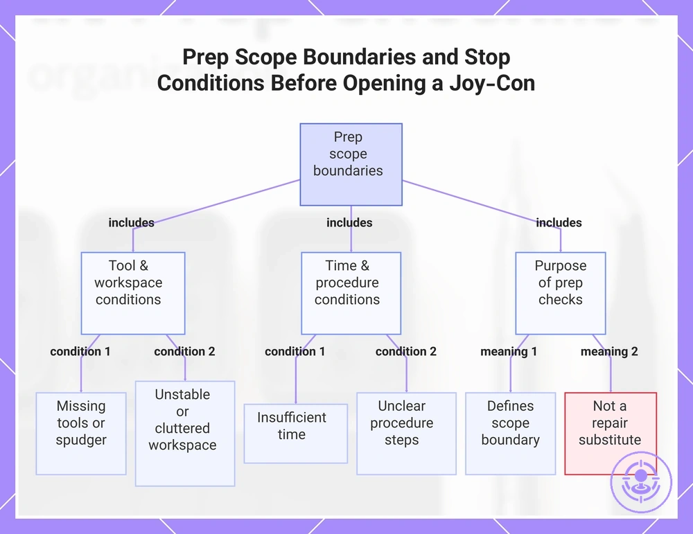
Prep scope boundaries and stop conditions before opening a Joy-Con
The prep phase covers the checks you make before any screw removal or shell separation begins. It covers readiness of tools, workspace, and time—if any condition isn't met, you risk damaging components or losing small parts.
Stop conditions that require a pause before opening include:
- Missing tools – the required screwdriver or spudger is not available.
- Unstable workspace – the surface is cluttered or poorly lit.
- Insufficient time – the task may not be possible to finish in one sitting.
- Unclear procedure – the steps for your model are not confirmed.
Prep checks are a scope boundary, not a substitute for the repair procedure—the Joy-Con drift repair kit hub covers the full process.
This chart shows the prep scope boundaries and stop conditions before opening a Joy-Con, including tool, workspace, time, and procedure conditions, and the purpose of these checks.
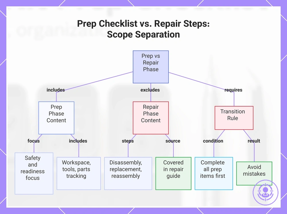
What belongs in prep vs what belongs in the step-by-step repair flow
Prep checks focus on safety and readiness; disassembly, replacement, and reassembly remain out of scope for this phase. This separation helps avoid mistakes.
The out-of-scope repair steps are covered in the step-by-step repair process guide.
Prep checks include:
- Workspace readiness
- Safety controls
- Tool staging
- Parts tracking
Repair steps (out of scope for this prep checklist):
- Disassembly
- Replacement
- Reassembly
This checklist covers only the prep phase; do not proceed to disassembly until all prep items are confirmed.
This chart clarifies what belongs in the prep phase versus the repair phase, highlighting the rule to complete all prep checks before starting disassembly.
When to halt DIY and use a guided repair path or official service
Stopping is the safer choice when prep conditions for using the Joy-Con drift repair kit raise risk or uncertainty that you cannot safely control.
Watch for these stop triggers before starting:
- Missing correct driver for any screw in the kit instructions
- Inability to control static near the circuit board or ribbon cables
- Uncertainty about connector orientation or release mechanism
- Work area that is unstable, cluttered, or poorly lit
- Discomfort or lack of confidence around handling battery-adjacent components
Uncertainty alone is reason enough to pause. A guided repair path can clarify the step and reduce the risk of damage.
Workspace Setup That Prevents Slips, Lost Parts, and Accidental Damage
A well-structured workspace can reduce slips, lost screws, and accidental tool damage during a Joy-Con drift repair kit job by controlling three key attributes: surface stability, clear visibility, and part containment. The effectiveness of each layout choice depends on how well it matches the repair environment. A stable surface reduces the risk of tools sliding, while adequate lighting helps you spot small screws before they disappear.
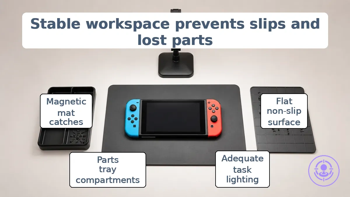
A distraction-free setup with organized cables and tools also reduces the chance of knocking over a container or dropping a screwdriver. Such layout choices typically do not affect the repair procedure but create conditions that can lower the risk of errors.
- Stability
- Use a flat, non-slip surface that does not shift during assembly.
- Secure the Joy-Con housing with a non-marking mat or holder.
- Visibility
- Position a task light to reduce shadows over the work area.
- Keep the workspace free of debris that can hide small parts.
- Containment
- Place a parts tray with compartments to organize screws by size.
- Use a magnetic mat to catch dropped metal components.
- Keep a clean zone around the repair area to reduce the risk of parts rolling away.
Stable surface, lighting, and visibility for tiny screws and connectors
For safe Joy-Con drift repair, you need a stable surface, adequate lighting, and clear visibility of tiny screws and connectors. Without these, even a well-matched replacement component can lead to misalignment or stripped threads.
Lighting angle reduces glare to improve alignment when seating connectors, and a stable surface enables controlled pressure to lower cam-out risk when driving tiny screws.
- Surface is flat, non-slip, and positioned at a comfortable working height.
- Light source is adjustable and positioned to minimize glare on tiny screws and connectors.
- Magnification (if needed) makes tiny screw heads and connector pins easier to see.
- Work area is free of clutter that could knock components out of alignment.
- Hand or wrist rest is available to steady the tool during fine adjustments.
These checks need no specialized equipment; a well-lit, stable desk surface typically meets them.
Clean zone and dust control to protect internal components during staging
Staging a Joy-Con drift repair kit in a clean zone can reduce the risk of dust and debris entering the internal components during assembly. Contamination from airborne particles during staging can compromise connector reliability and increase the chance of debris interfering with contact points.
A tidy work area with a covered surface limits lint and dust accumulation. Parts staging should minimize exposure time to reduce debris risk. These actions apply only to the staging environment and do not involve cleaning the repair kit components.
These actions maintain a clean staging environment:
- Designate a clean staging area away from high-traffic zones.
- Cover the work surface with a lint-free mat or cloth.
- Keep all repair kit components in sealed containers until use.
- Remove dust from hands and clothing before handling parts.
- Return unused components to sealed storage immediately after staging.
Safety precautions for electronics handling before the housing is opened
Safety precautions before opening the Joy-Con housing reduce the risk of electrical short circuits and component damage during repair with a drift repair kit. The most critical condition is achieving the proper device state before opening the housing.
The diagram organizes the primary safety controls by risk priority, indicating which checks to perform first before disassembly.
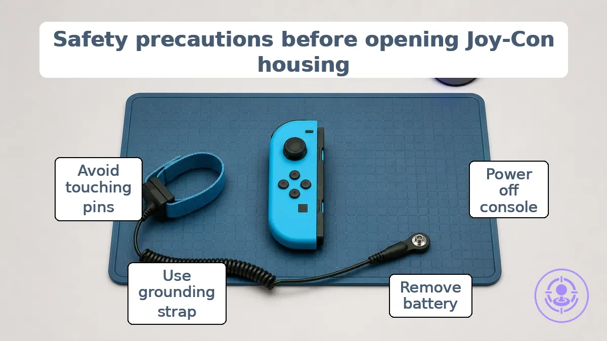
Work through the checklist in order, starting with the highest‑risk control — electrical isolation — then moving to static control and connector handling.
- Power off the Nintendo Switch console and detach the Joy-Con to remove power flow and help prevent an unintended short.
- Remove any battery or external power source to isolate the circuit.
- Work on a static‑safe surface and use a grounding wrist strap to reduce the risk of ESD damage to sensitive components.
- Avoid touching the internal connector pins with bare hands or metal tools; static discharge may cause intermittent faults after reassembly.
- Use a low‑force, non‑conductive tool when prying the battery connector to help avoid bending pins or shorting contacts.
- Keep the workspace clear of conductive debris and liquids that could create an unintended path for current.
- Handle ribbon cables by their edges and avoid pulling on the wires to help prevent tearing or loosening the connector.
- If the battery appears swollen or damaged, stop and do not proceed; a damaged battery can leak or ignite when stressed.
Following these precautions does not guarantee damage‑free repair, but it lowers the likelihood of an electrical fault during disassembly.
Power-down, detachment, and handling steps that reduce short-risk
Before using a Joy-Con drift repair kit, power off the Joy-Con and detach it from the console. This reduces the chance of an active power path during handling, lowering short risk.
These external checks confirm the device is safe to handle before you proceed:
- Confirm the Joy-Con is fully detached from the console.
- Verify that the console itself is powered off and disconnected from any power source.
- Check that no charging cables are attached to the Joy-Con or console.
- Place the Joy-Con on a clean, dry, non-conductive surface.
- Work in a static-safe area away from moisture.
- Avoid pressing any buttons while handling the Joy-Con to reduce accidental input.
- Keep the repair tool away from metal contacts until the device is confirmed powered down.
These are external checks only, not internal disassembly. They do not guarantee short prevention—safe handling requires completing each check before proceeding.
Anti-static precautions and grounding practices for small electronics
Taking anti-static precautions when preparing to repair a Joy-Con can reduce the chance of damaging sensitive internal parts. Even a static discharge too small to feel can harm circuit components, so controlling static before touching the board is critical.
How well static control works depends on handling conditions like humidity and whether you properly ground yourself. Before opening the controller, make sure the following grounding and environment controls are in place:
- Wear an anti-static wrist strap grounded to a work surface or unpainted metal.
- Touch a grounded metal object, such as a water pipe or a metal table leg, before handling components.
- Use an anti-static mat connected to a common ground point.
- Keep humidity in your work area at a moderate level; dry air increases static buildup.
- Remove plastic, Styrofoam, and synthetic fabrics from the work area because they hold static charges.
- Store replacement parts in anti-static bags until you are ready to install them.
- Avoid working on electronics when wearing clothing that generates static, like wool or nylon.
Battery and Connector Cautions That Affect Safe Prep and Staging
Battery-adjacent areas and delicate connectors in a Joy-Con drift repair kit require low-force, low-risk handling from the start because ribbon cables near the battery are fragile and excess strain or puncture can create hazards such as connector failure or battery-area damage. Follow these do-not behaviors to keep the staging area safe:
- Do not pull on ribbon cables; use the designated latch or tab to release delicate connectors.
- Do not apply force to battery terminals or connectors; low-force handling reduces strain and short-circuit risks.
- Do not bend or pinch flexible ribbon cables near the battery compartment; bending can cause internal fracture.
- Do not use metal tools to pry battery connectors; plastic tools or cable latches reduce puncture hazard.
- Do not attempt to disconnect battery wires by pulling on the wire itself; grip the connector housing.
- Do not leave tools or loose components resting on top of the battery area; weight can create unintended pressure.
- Do not skip inspection of connector latches before applying separation force; a stuck latch indicates possible strain.
Tools and Supplies to Stage Before You Start the Joy-Con Repair
Staging the right tools before opening a Joy-Con keeps you from having to improvise mid-repair, which can strip screws or damage components. A precision screwdriver with a tri-wing Y00 bit is often required to match the small recessed screws; using the wrong driver rounds the heads and complicates the repair.
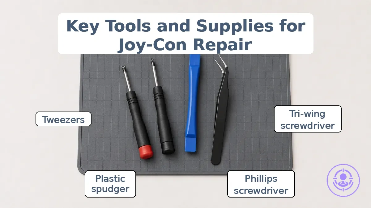
Using the right screwdrivers and screws helps ensure the tri-wing and Phillips heads fit snugly, reducing the chance of cam-out. A plastic spudger provides a non-marring prying surface that protects the shell from scratches, while tweezers help guide fragile ribbon cables without tearing.
Organizing screws on a magnetic mat or small parts organizer prevents misplacement and helps you keep track of reassembly order.
The checklist below groups tools by function. Must-have items are necessary for safe disassembly; nice-to-have items improve stability and reduce risk.
Must-have tools
- Tri-wing Y00 precision screwdriver (fits the small recessed tri-point screws on the Joy-Con shell)
- Phillips #00 precision screwdriver (for internal screws such as battery and bracket fasteners)
- Plastic opening tool or spudger (non-marring, helps separate the shell without scratching)
- Tweezers (for handling delicate ribbon cables and small screws)
- Parts organizer or magnetic mat (keeps screws grouped and helps prevent rolling away)
Nice-to-have stabilizers
- Replacement tri-wing screws (in case originals strip during removal)
- Anti-static wrist strap (minimizes electrostatic discharge risk)
- Magnifying lamp or headlamp (improves visibility of small components)
Core kit tools to verify for fit and control before first screw removal
Correct driver fit can reduce the risk of stripping a tri-wing screw during first removal, especially given the shallow thread engagement of Y00 screws in Joy-Con housings. Before starting, check the following to maintain stable engagement and controlled pressure and reduce the chance of cam-out.
- Confirm the driver tip is tri-wing (Y00) and seats fully into the screw head.
- Check the driver shaft is perpendicular to the screw for steady angle.
- Ensure the driver handle allows controlled pressure without slipping.
- Verify the driver tip is not worn or rounded (increases cam-out risk).
- Gently seat the driver to test fit and feel for engagement without force.
- Confirm the screw head is free of debris that could cause the driver to slip.
- Check that your work surface and hand position allow steady angle throughout the turn.
If the driver does not seat fully, the screw may be a different type or the tip may need replacement. These checks lower the risk of a stripped screw before removal starts but do not replace careful handling during the first turn.
Support Tools That Reduce Slipping and Part Stress During Handling
Non-marring spudgers, plastic opening tools, and precision tweezers help reduce slipping and part stress during handling. Used correctly, they minimize the risk of scuffing, tearing, or dropping delicate components during disassembly. Before disassembly, check that your Joy-Con drift repair kit includes the tools needed for each task.
- Grip – Precision tweezers with a textured grip can provide steady control when handling small screws and connectors, reducing slip.
- Non-marring separation – A non-marring spudger can pry ribbon cables and housing clips while helping avoid scuffing or surface damage.
- Part pickup – A plastic opening tool can lift delicate flex cables and adhesives with its thin, dull edge, helping avoid tearing.
- Storage – A parts tray with compartments can keep screws and small components organized, helping prevent accidental loss or stress from searching.
- Anti-slip work surface – A silicone mat can provide a stable, non-slip base that holds the Joy-Con in place during handling.
- Static control – An anti-static brush can remove debris without building up charge that could stress sensitive electronics.
- Suction lift – A small suction cup can lift the battery or display panel while helping avoid applying pinching force that may damage connectors.
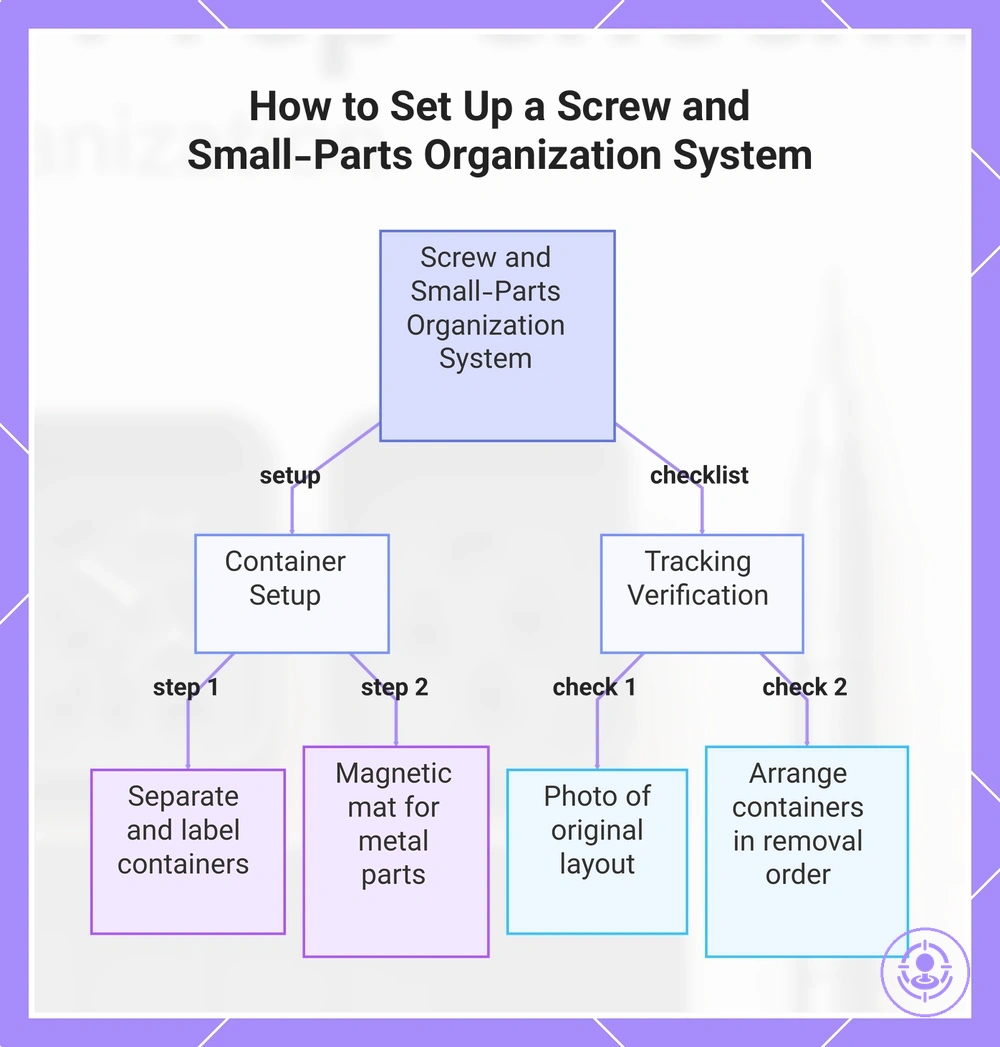
Screw and small-parts organization system to prevent mix-ups
Setting up a screw and small-parts organization system before disassembly prevents mix-ups and lost parts during reassembly. This checklist verifies that your system tracks each part from removal to reassembly.
- Separate screws, springs, and shields into their own containers or compartments.
- Label each container or zone with the part name or the disassembly step number.
- Place small metal parts on a magnetic mat to prevent them from rolling away.
- Keep the parts tray or labeled containers within arm's reach throughout reassembly.
- Use color-coded labels or stickers to distinguish similar-looking parts from different sections.
- Take a photo of the original screw layout before removal to confirm placement later.
- Arrange containers in the order parts are removed (outer casing first, then internal components).
- Ensure all containers are stable and secure before moving the workspace or transporting parts.
This chart shows the key setup steps and verification checks to prevent mix-ups during disassembly and reassembly.
Screw tracking with a magnetic mat, parts trays, and labeled zones
Screw tracking with a magnetic mat and labeled zones reduces wrong placement risk by creating a visual map that improves retrieval accuracy during reassembly.
Setting up labeled zones in reassembly order before starting the Joy-Con drift repair kit process helps maintain left and right separation and reduces the chance of swapping screws. This checklist helps verify that your screw tracking system is ready for safe reassembly:
- Place a magnetic mat on a flat work surface near the parts tray.
- Assign labeled zones for each screw group based on disassembly order, separating left and right groups into distinct zones to avoid cross-use.
- Label each zone with a clear identifier such as screw location or function.
- Keep a small parts tray nearby to hold non-magnetic components or extra screws.
- Check that each screw sits securely in its zone before moving to the next step.
- Verify that the zone layout matches the reassembly sequence to reduce errors.
Small Parts Containment for Springs, Caps, and Fragile Components
When preparing a Joy-Con drift repair kit, keeping springs, caps, and other fragile components contained reduces loss risk and helps prevent contamination. A container with a secure lid lets you work one-at-a-time and keeps parts from mixing. This pre‑flight check focuses on staging, not on the repair itself.
Use these containment habits to lower loss risk and contamination during staging.
- Use a small parts storage box with compartments for springs and caps.
- Keep the lid closed when not actively removing a part.
- Place fragile components in a separate container to avoid damage.
- Remove and organize parts one-at-a-time to avoid mixing parts.
- Label compartments if multiple spring sizes exist.
- Check that containers are clean and free of debris.
- Secure lids after each step to minimize loss risk.
Documentation habits that protect orientation and reassembly accuracy
Lightweight documentation—such as a quick photo or note—records connector and cable orientation before disassembly, reducing reassembly errors on similar-looking ribbon cables.
Each connector has a specific orientation attribute: the cable's routing path, the latch position, or the left/right placement. A photo or labeled note can record these attributes, mapping them to their correct positions. For example, photographing the left and right shoulder button cables before removal helps prevent swapping them during reassembly. Focus documentation on orientation details rather than the entire assembly process.
These key checkpoints prevent common orientation and reversal errors during reassembly:
- Photograph each connector before disconnecting, showing its cable route, latch orientation, and routing path through clips or guides.
- Label cables with their corresponding connector numbers or left/right markers.
- Note the order of stacked ribbon cables (e.g., which cable sits on top).
- Mark the front/back orientation of flexible circuits before removal.
- Create a reference photo of the full internal layout before starting.
- Verify that each label matches its intended destination before reassembly.
- Store photographs and notes in a single, accessible file for sequential reference.
This chart shows the recommended documentation habits and key checkpoints to prevent orientation and reversal errors during device reassembly.
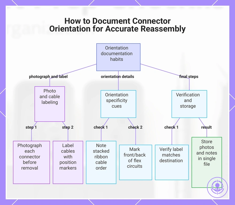
Photo checkpoints for cable routing, connector orientation, and part order
Photo checkpoints for cable routing, connector orientation, and part order in a Joy-Con reduce reassembly mistakes by preserving the original arrangement as a reference.
This approach is most useful when the cable path is not obvious or when multiple connectors share similar shapes. A few targeted snapshots show how each ribbon or wire was positioned before disassembly.
- Overall cable routing path before any connector is detached
- Connector orientation showing which side faces up or which edge aligns with a notch
- Part order of stacked components, such as brackets or shields, before removal
- Close-up of any latch or locking tab before release
- Angle of the cable where it bends around a screw post or frame edge
- Position of any adhesive strip or tape that secures the cable
- Sequence of connectors on a shared cable, especially when pin counts differ
- Final assembly photo after routing is confirmed, before closing the shell
Limit checkpoints to the moments hardest to recall; too many photos slow the process. The goal is a reliable reference that supports careful handling, not to replace it.
Simple labeling to avoid left-right swaps and reversed alignment
When reassembling a Joy-Con drift repair kit, simple labeling of each part group before removal can reduce the risk of left-right swaps and reversed alignment errors, especially for similar-looking components like shoulder buttons or trigger assemblies.
Clear marks and tape tags help maintain orientation, but labeling works only when applied consistently and kept minimal. The following checkpoints help prevent common labeling mistakes that cause swap risks and alignment errors:
- Mark each small part with a tape label indicating left or right orientation before disassembly.
- Use alignment marks on flexible cables to avoid reversed connections during reattachment.
- Group screws from each component together and label the group by original location.
- Apply a quick label before removing any part that has a symmetrical counterpart.
- Keep labels visible and on non-contact surfaces to avoid interfering with reassembly.
- Remove labels only after final verification of correct placement and alignment.
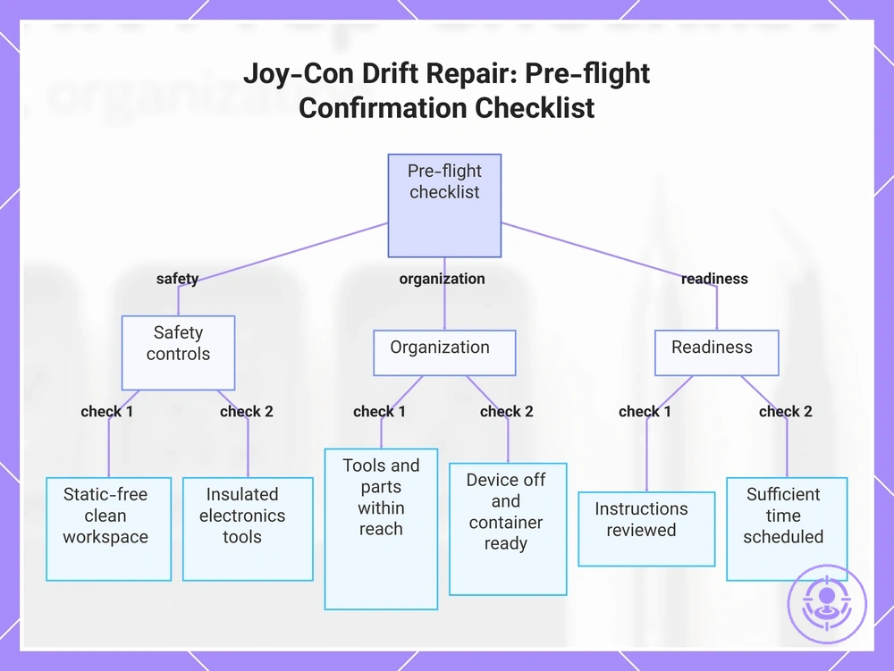
Pre-flight confirmation checklist before the first opening step
The pre-flight confirmation checklist is the final check before the first opening step of the Joy-Con drift repair kit. It verifies safety controls, organization, and readiness. It does not guarantee success, but it helps reduce avoidable errors. Run this verification separately from the repair instructions to catch overlooked preparations.
Before you open the Joy-Con, run through these grouped checks for safety, organization, and readiness:
Safety controls:
- Work area clean and free of static hazards. If not, pause and clear.
- Tools insulated and suitable for electronics. If not, pause and find appropriate.
- No liquids or clutter near the work surface. If present, pause and remove.
Organization:
- All required tools and parts within reach. If missing, pause and gather.
- Joy-Con powered off and disconnected from console. If connected, pause and disconnect.
- Container ready for small screws and components. If not, pause and prepare.
Readiness:
- Repair instructions accessible and reviewed. If not, pause and review.
- Enough time set aside to open without rushing. If short on time, pause and schedule later.
- Stopping rule: If any condition fails, correct it before proceeding. Do not proceed until all conditions pass.
This chart outlines the pre-flight confirmation checklist with three groups of checks to ensure safety, organization, and readiness before opening a Joy-Con.
Safety confirmation: static control, power state, and controlled tool pressure
Before you apply any opening force, verify that static control is active, the device power state is off, and the pressure tool is set to a controlled level. These three conditions lower the risk of short-risk, component damage, and slip risk.
Should any of these checks fail, review the mistakes to avoid before you begin section before proceeding.
- Verify that the device power state is off and no battery or power source is connected.
- Confirm that your workstation includes static control measures such as an anti-static mat or wrist strap.
- Set your opening tool to a controlled pressure level that matches the tool's guidance.
- Check that the tool tip is aligned to apply steady pressure without sudden force.
- Ensure that the area around the seam is clear of debris that could alter pressure distribution.
- Recheck the power state after any preparatory steps to ensure no accidental power-on.
- Confirm that static control is maintained throughout the process by avoiding synthetic fabrics or ungrounded surfaces.
- Test the pressure tool on a non-critical surface to confirm controlled pressure and reduce slip risk.
Organization Confirmation: Screw Map, Containers, and a Clean Reassembly Zone
Before starting a Joy-Con drift repair, confirm that the screw map is correctly laid out, containers have closed lids, and the clean reassembly zone is clean. This reduces the risk of wrong screw placement and missing parts later.
Verify each of the following before opening the Joy-Con. Do not proceed until all checks are satisfied.
- Screw map is labeled and matches the Joy-Con model’s screw layout.
- Each container has a closed lid to keep small parts from scattering.
- Containers are placed within easy reach to avoid disturbing the screw map order.
- The reassembly zone is wiped clean and free of dust that could enter the housing, and the work surface is cleared of debris, to reduce contamination risk.
- Screw map is positioned in a visible spot to guide retrieval accuracy during reassembly.
- Containers follow the disassembly sequence so screws can stay in the order shown on the map.
Execution readiness: time buffer, distraction control, and a stopping rule
Rushing through a Joy-Con drift repair kit job increases the risk of errors and rushed handling.
Before you begin, review this short checklist:
- Set a time buffer – Allocate extra time around the repair window so that delays do not force hurry.
- Remove distractions – Silence notifications, close unrelated tabs, and tell others you are not available to maintain focus.
- Define a stopping rule – Decide in advance when you will pause, such as after a step that causes frustration or after a set time without progress.
This checklist does not guarantee a trouble-free job, but it does reduce errors from rushing or losing focus.