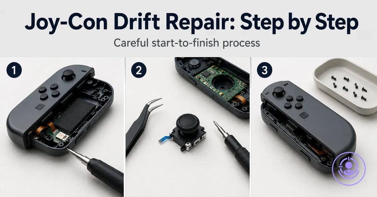
Step-by-Step Joy-Con Drift Repair Using a Joy-Con Drift Repair Kit
Step-by-step Joy-Con drift repair using a Joy-Con drift repair kit replaces a worn joystick module and can help reduce unwanted movement when other fixes have not worked. Results depend on correct seating of components, careful screw handling, and the condition of the parts being removed.
For many users, Joy-Con drift first shows up as unwanted movement in games. Deciding to replace the joystick module rather than using temporary cleaning can be the next step. This workflow helps avoid common mistakes such as stripping screw heads, damaging ribbon cables, misaligning the battery connector, or breaking plastic clips.
The repair typically includes preparing the workspace, opening the Joy-Con shell, disconnecting the battery and ribbon cables, removing the old joystick module, installing the replacement, reassembling the controller, and testing for drift.
These steps assume a compatible Joy-Con drift repair kit with the necessary tools and replacement parts.
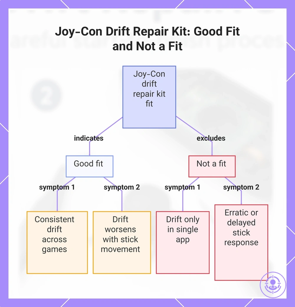
When this repair flow is the right fit and what it will not fix
A Joy-Con drift repair kit is a good fit when stick drift symptoms stem from a worn or contaminated joystick module, but it is not a fit when the issue lies outside the module's mechanical boundary—such as electrical failures or calibration errors at the system level.
Stick drift symptoms often trace back to a worn or contaminated joystick module; when the drift pattern matches typical module degradation, replacing the module with a repair kit can restore normal function.
Drift-like behavior may also stem from issues other than the joystick module; those cases need a different diagnosis and fall outside this replacement.
The lists that follow show when this replacement applies based on symptom pattern and expected outcome.
Good fit
- Stick drift that is consistent across multiple games or menus
- Drift that worsens with physical movement of the stick
- Drift that persists after a controller restart or re-pair
- Visibly worn or loose joystick module
- Symptom pattern matches known joystick-module failure (e.g., upward drift in left stick)
Not a fit
- Drift that appears only in a single application or screen
- Stick response that is erratic or delayed rather than drifting
- Buttons or triggers that are unresponsive while sticks work normally
- Controller not powering on or pairing properly
- Drift that disappears after a system update or calibration
- Physical damage to the controller housing or circuit board
This chart shows the symptom patterns that indicate when a Joy-Con drift repair kit is a good fit and when it is not, based on drift behavior and other issues.
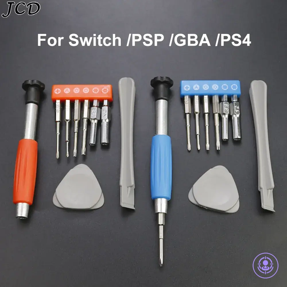
Tools and Replacement Parts You Will Use During the Repair
Joy-Con drift repair is more likely to succeed when the tool category matches the screw and connector constraints. The tools and parts below are grouped by job: opening, fastening, connector handling, module replacement, and screw organization.
Each tool or part includes its purpose, handling constraint, and the failure risk if missing or mismatched. The image below labels the tools and parts used during the repair.
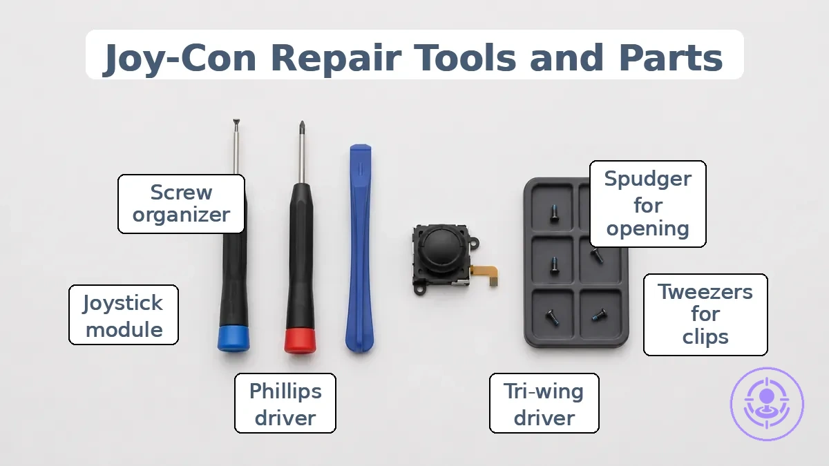
Opening Tools
- Spudger (plastic opening tool) – separates shell seams and releases clips. Use only at seam gaps to avoid marring the plastic. Prying with a metal tool can crack the shell clips.
- Tweezers – lift the edge of stubborn clips or adhesive. Apply gentle pressure. Slipping can scratch the motherboard.
Fastening Tools
- Tri-wing/Y-type driver (Y00 size) – removes the three‑pointed exterior screws. The bit must seat fully into the screw head. A worn or wrong‑size driver often strips the head, making removal difficult.
- Phillips/cross driver (small size) – loosens internal cross‑head screws. Keep the driver perpendicular to the screw. Off‑angle force can cause cam‑out and damage the recess.
Connector Handling
- Tweezers – flip the small ribbon‑cable latches on the motherboard. Use the tip to lift the latch straight up. Pulling the flex cable instead of the latch can tear the cable.
- Spudger (flat end) – gently press on connector edges if latches are stiff. Avoid metal tools that may short contacts.
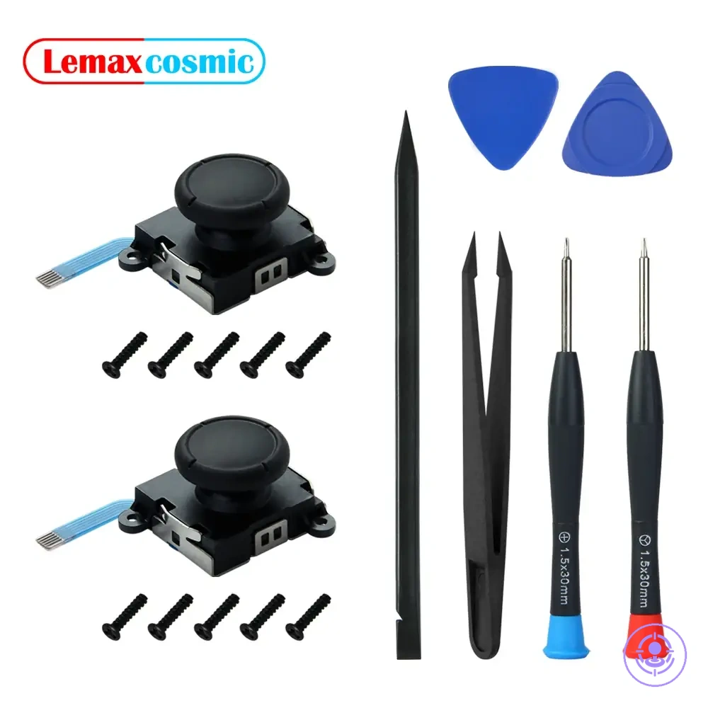
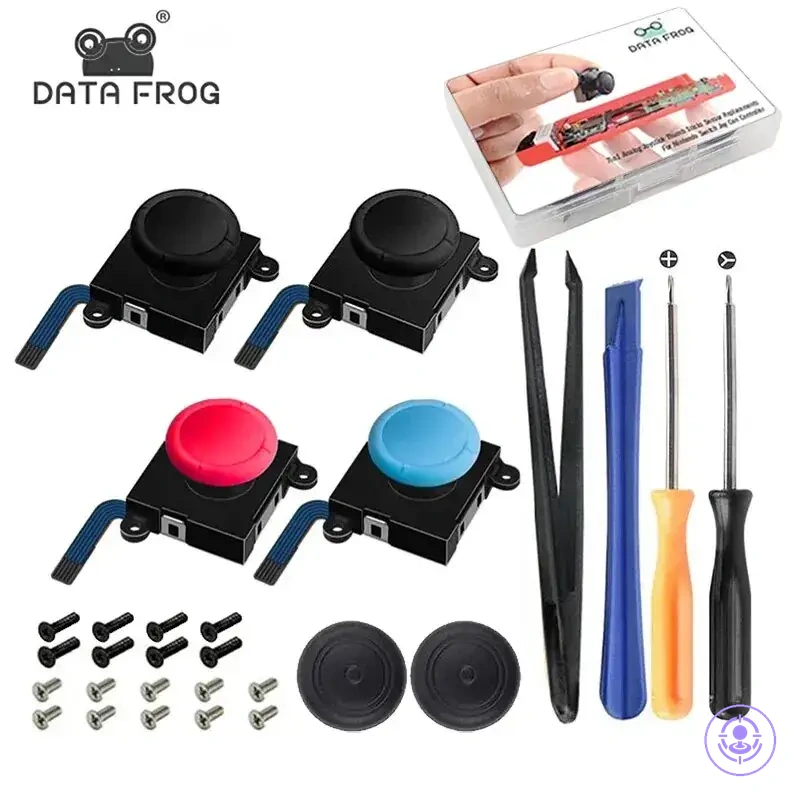
Module Replacement
- Joystick module – replaces the worn analog stick. Align the flat edge of the module with the slot on the shell. Forcing it in the wrong orientation bends the connector pins.
- Tweezers – guide the ribbon cable into the new module’s socket. Ensure the cable is fully seated before closing the latch. A loose connection can cause erratic stick behavior.
Screw Organization
- Screw organizer (magnetic parts dish or labeled container) – keeps screws separated by length and thread.
- Exterior and interior screws differ; mixing them can strip threaded holes or cause short circuits if a longer screw presses into the board.
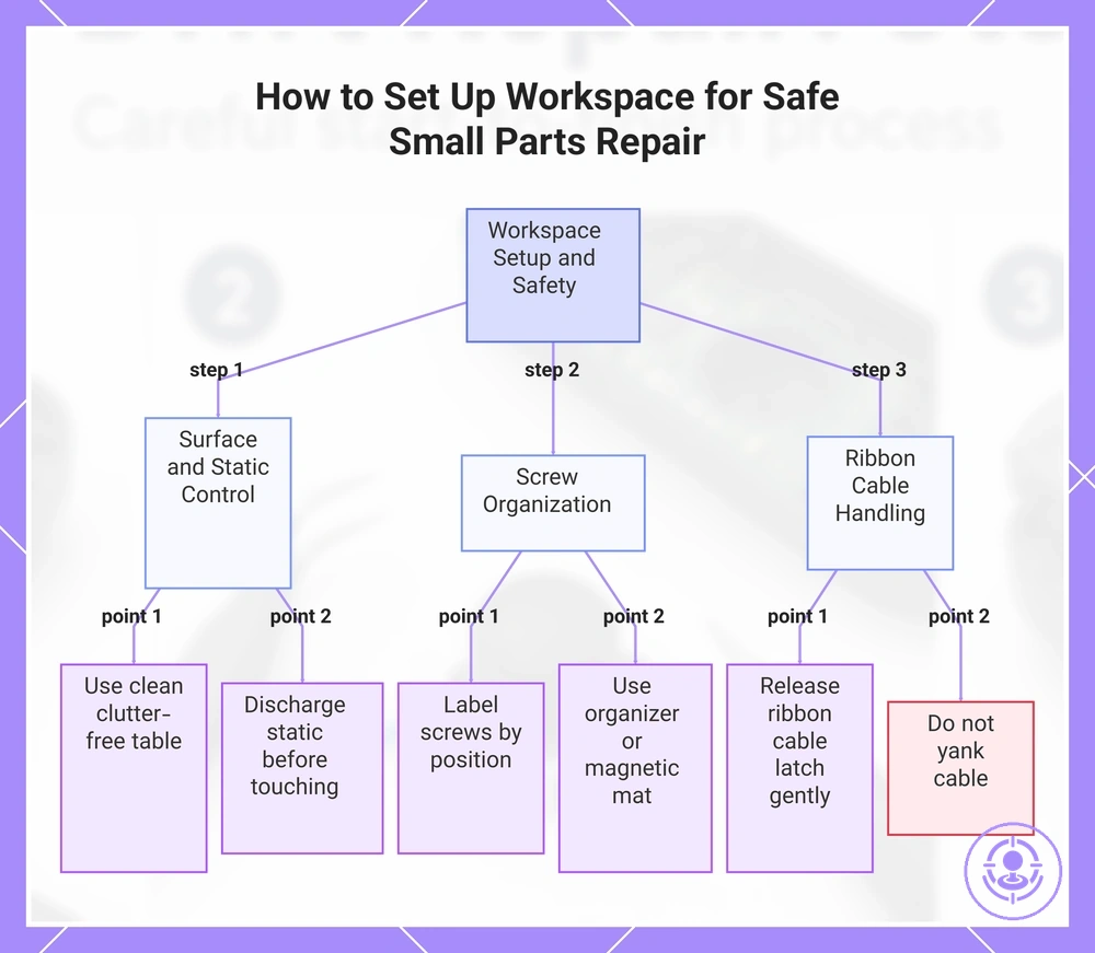
Worksurface setup and safety handling for small parts and screws
Start with a clean, stable surface and organize each screw as you remove it to prevent lost parts and misaligned reassembly. Controlling static and dust reduces the risk of intermittent input after the repair.
Ribbon cables are fragile — pulling them without releasing the connector latch can tear conductors or bend pins. The prep checklist and safety steps include guidance on screw organization and ribbon cable handling to help prevent first-time mistakes.
- Use a clean surface — dust and debris on contacts can cause intermittent input later.
- Remove small screws one at a time, label them by position, and place them in a screw organizer or magnetic mat mapped to their original locations.
- Handle each ribbon cable by its latch; apply gentle pressure straight up to release, do not yank the cable.
- Touch a grounded metal object before touching components to reduce static-related intermittent issues.
- Work on a clutter-free table to avoid tools or parts accidentally knocking loose connections.
With your workspace set up and these safety steps followed, you can move on to disassembly.
This chart outlines the essential preparation steps, including surface cleaning, static control, screw organization, and ribbon cable handling, to avoid common mistakes during repair.
Disassembly order for opening the Joy-Con without damage
A controlled disassembly order reduces the risk of screw stripping, clip cracking, and ribbon cable damage.
The image shows the key checkpoints for the disassembly order: outer screws, shell seam, battery connector, and ribbon cable area.
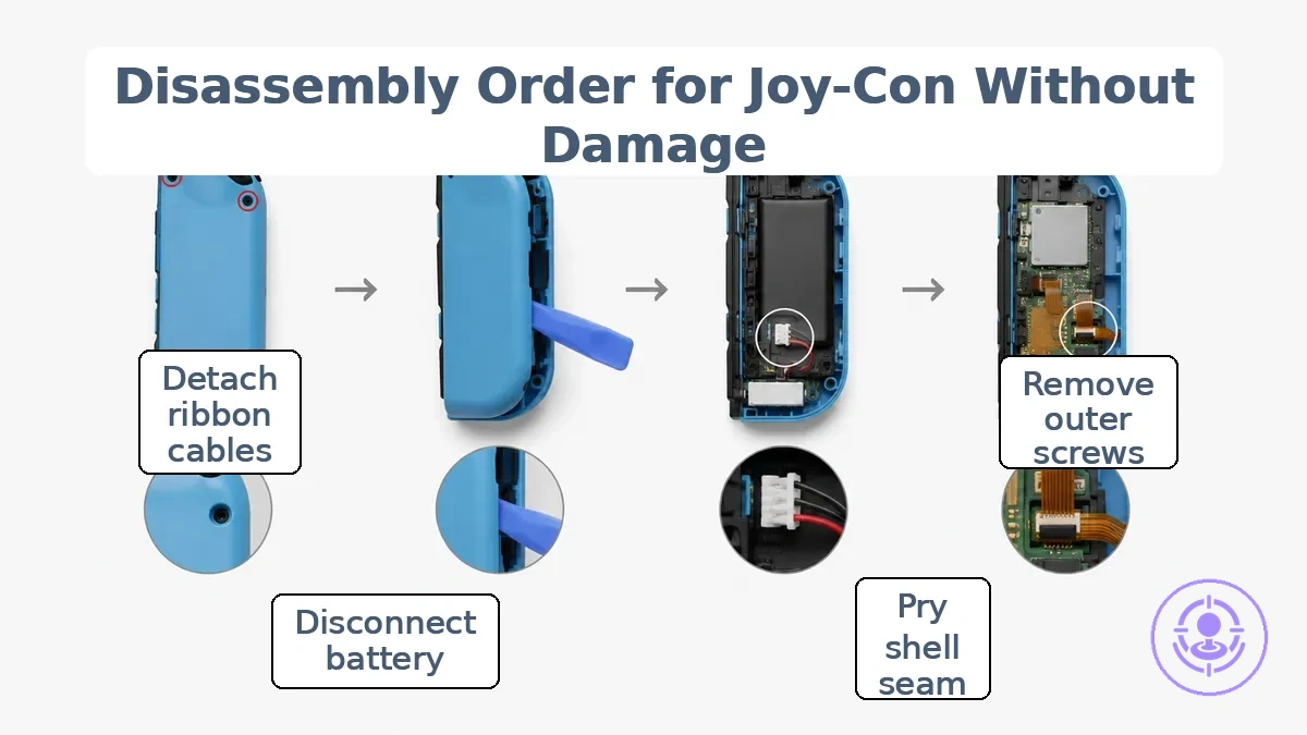
- Remove the four outer screws using the correct driver fit—a tri-point Y00 or Y1—to avoid stripping the recesses.
- Gently pry the shell seam apart, freeing the plastic clips along the edge to prevent cracking or breaking.
- Do not force the clips; if resistance is met, double‑check that all outer screws have been removed before continuing.
- Disconnect the battery connector to isolate power and prevent shorts or accidental contact.
- Open the connector latches and detach the ribbon cables carefully to avoid tearing the delicate traces.
- If present, lift the battery bracket by removing its two screws to avoid damaging the bracket.
- Remove any interior screws securing the main board, then separate the shell halves without forcing any joint.
The next sub-sections cover the highest-risk moments in the disassembly order.
Remove the outer screws with the correct driver and keep screw positions organized
Use a tri-wing or Y-shaped driver with a correct driver fit — the tip must seat snugly into the outer screw heads to prevent stripping. Follow this checklist to avoid stripped screws and mix-ups during reassembly.
- Seat the driver tip fully into the screw head for maximum grip.
- Apply steady downward pressure while turning counterclockwise to maintain bite and reduce stripping risk.
- Keep the driver perpendicular to the screw head and turn slowly to avoid angled force.
- Label or map each screw's original hole immediately after removal to preserve screw position.
- Place screws in a partitioned container or separate bags according to their location.
- If a screw resists turning, check for paint or debris before increasing force to avoid rounding the head.
Open the shell while protecting clips and internal ribbon cables
Cracked clips or snapped ribbon cables can happen if you pry the shell seam carelessly; using a controlled, hinge-like opening motion directed away from the ribbon cable path lowers that risk.
These safe and unsafe cues help you keep clips intact and avoid snagging cables.
- Do: Insert a spudger at the shell seam and apply gentle, controlled pressure to separate the halves.
- Avoid: Prying near the clips or using a sharp tool that could crack the plastic.
- Do: Lift the shell in a hinge-like opening motion while keeping the ribbon cable slack to help prevent snagging.
- Avoid: Pulling the shell apart quickly or twisting it, as this stresses the clips and can snap the cable.
- Do: Align the ribbon cable path and lift it clear of the lower shell before fully opening.
- Avoid: Forcing the shell open if you feel resistance—stop, re-check the seam, and ensure no cable is caught.
Disconnect the battery first and release ribbon cable latches safely
Disconnecting the battery is the first internal safety step before touching any other connector. Following this order helps prevent electrical shorts and torn ribbon cables.
- Locate the battery connector and disconnect it by gently separating the connector from its socket; do not pull the wires.
- Identify the ribbon cable latch and lift the locking tab using gentle pressure; support the connector while releasing the latch.
- Once the latch is released, slide the ribbon cable straight out; lift by the tab, not the cable.
If you feel resistance, recheck the latch position and apply gentle pressure; avoid forcing the cable.
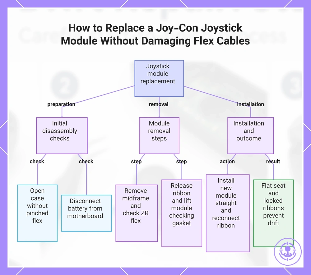
Replace the joystick module and re-seat connectors without bending flex cables
Replacement succeeds when the joystick module seats flat and ribbon connectors are fully seated. Proper alignment prevents drift or skew, while improper seating risks intermittent input. Refer to the joystick replacement steps for a detailed walkthrough.
The steps below outline the replacement and help prevent bent flex cables.
- Open the Joy-Con case by releasing the back panel clips and lifting it away, verifying no flex cable is pinched.
- Disconnect the battery connector from the motherboard using a spudger, verifying it is fully detached.
- Remove the midframe after unscrewing it and carefully lifting it, verifying the ZR button flex cable is not under tension.
- Release the joystick ribbon cable by flipping up the ZIF connector latch and pulling the cable straight out after ensuring the latch is fully open.
- Remove the two screws holding the joystick module, lift the module straight out, and check that the thin gasket around the joystick hole remains undisturbed.
- Install the new joystick module: insert straight, align screw holes, and tighten screws. Reconnect the ribbon cable, close the ZIF latch until it clicks, and gently tug the cable to confirm it is locked.
This chart shows the step-by-step process to replace the joystick module, including key checks to avoid bent flex cables and ensure proper seating.
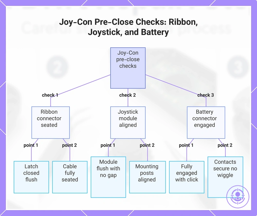
Confirm Connector Seating and Joystick Alignment Before Closing the Shell
Three pre-close checks prevent reopening the Joy-Con: the ribbon connector fully seated with the latch closed, the joystick module flat and aligned, and the battery connector fully engaged.
These pre-close checks catch intermittent inputs, alignment issues, and no-power conditions before you close the shell.
- Ribbon cable latch closed — press the latch down fully until it is flush; a half-closed latch can cause intermittent button or stick responses.
- Ribbon cable fully seated — confirm the cable is inserted all the way to the stop; partial insertion can lead to missing inputs or intermittent connections.
- Joystick module flush — ensure the module sits flat with no gap; a rocking module causes erratic stick movement.
- Joystick mounting stable — check that the mounting posts align with the board holes; misalignment can introduce drift or inconsistent response.
- Battery connector fully engaged — push until you hear a click and the connector sits flush; a half-connected battery can result in no power or random disconnects.
- Battery connector contacts secure — verify the connector does not wiggle when lightly pushed; loose contacts can cause intermittent power loss.
This chart shows the three essential pre-close checks to verify before closing the Joy-Con shell, preventing common issues like intermittent inputs, drift, and power failure.
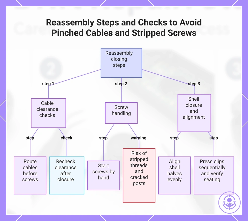
Reassembly order and closing tips to avoid pinched cables and stripped screws
Reassembly should follow the reverse order of disassembly and keep ribbon cables and wires clear of screw posts and housing seams to avoid pinched cables and cross-threading.
Following this order prevents pinched cables, cross-threading, shell stress, and stripped screws, and helps you avoid common mistakes during repair.
- Route all cables along designated paths before inserting any screws, verifying that no cable lies over a screw post or near a seam edge to reduce the risk of pinched cables.
- Start each screw by hand, turning it counterclockwise until the thread drops into place, then clockwise to seat it, to prevent cross-threading in tight screw posts.
- Tighten screws only until you feel a firm stop; over-tightening can strip threads or stress the shell.
- Snug stop: screw is secure but not forced; shell typically remains flat.
- Over-tighten: screw continues to turn; risk of stripped threads or cracked posts.
- Align the two halves of the shell evenly along all seams before pressing clips into place; a misaligned seam can prevent clips from engaging fully.
- Press clips closed in sequence, starting from one side and working around the device. Listen for each clip to seat; a gap or uneven closure indicates a clip may be stuck or a cable may be trapped.
- After closing, recheck cable clearance by gently opening the seam slightly and looking for any visible ribbons or wires near screw posts to catch an overlooked pinch before it causes damage.
For additional risk control, pay attention to ribbon cable routing and battery connections, and tighten screws only to a snug stop.
This chart shows the key steps and checks to avoid pinched cables, stripped screws, and other common reassembly mistakes.
Route ribbons cleanly and ensure the battery connector is fully seated
Verify two checks: the ribbon route has clearance to avoid pinching, and the battery connector is fully seated to prevent power issues. A pinched ribbon can block proper connector locking, while a loose battery connector can cause no power or boot failures. The cues below help confirm both checks before final assembly.
- The ribbon lies flat in its channel with no visible folds or bends: indicates sufficient clearance and helps prevent pinch risk.
- The connector clicks audibly when pressed down: indicates the latch is fully engaged.
- The top of the connector sits flush with the board surface: indicates it is seated correctly.
- No gap is visible between the plug and socket: indicates complete engagement.
Tighten Screws to a Snug Stop and Avoid Cross-Threading or Over-Torque
A snug stop means the screw is tightened just enough to hold the shell firmly.
These checks help prevent stripping and frame stress:
- Align the screw straight into the hole, turn it backward until you feel a click, then thread forward to prevent cross-threading.
- Check that the driver bit fits snugly in the screw head to reduce the risk of cam-out and a stripped recess.
- Tighten only until the screw stops turning easily. If resistance suddenly increases, stop and back off to prevent over-torquing the shell.
- If the screw feels tight but the shell still moves, loosen and restart the thread to confirm alignment before final snugging.
Quick function checks after reassembly before calibration and full testing
Quick function checks confirm the controller powers on and registers inputs before calibration; a failure usually indicates a loose connector or misseated ribbon. The checklist below verifies power, stick movement, and button response, and explains what each failure suggests.
- Power on – press the sync button or insert the controller; if no LED or connection appears, the battery connector may be loose.
- Indicator behavior – after pairing, flashing or no player LED indicates a battery or main ribbon seating issue.
- Stick movement – move the stick in all directions and press it down; no response or erratic movement suggests the stick ribbon is misaligned or the connector is not fully inserted.
- Button response – press each face button, shoulder button, and SL/SR; a missing input usually indicates the corresponding ribbon cable is not properly latched.
- Home button – if the Home button does not wake the controller or open the menu, the ribbon may be folded or not seated flat.
- Motion controls – tilt the controller; if the gyro does not respond or freezes, the IMU ribbon could be loose or damaged.
- Screenshot / capture button – test button press; failure often links to the same ribbon as the Home or a shared latch point.
- Sync button – press while pairing; if no pairing mode starts, the sync button ribbon may not be making contact.
Failures in these checks most often come from a loose battery connector, a ribbon cable not fully inserted, or an unclicked latch. Re-check the reassembly steps one stage back instead of moving to calibration immediately. For detailed calibration and testing after repair, see the linked guide.
If the controller looks assembled but inputs are wrong — for example, stick drift without touching — a quick re-check usually resolves it. Open the shell and verify the stick module's ribbon is seated flat in its connector and the latch is pressed down completely.
Here are product examples that may make comparison easier. Before buying, always review the compatibility criteria, essential features, and product details.

How Long a First-Time Joy-Con Drift Repair Usually Takes and Why It Varies
A first-time Joy-Con drift repair typically takes between 30 minutes and two hours, but this time range varies widely based on your experience and the condition of the controller.
Two steps typically take up most of the time: removing stubborn screws that may be stripped or tight, and cautiously detaching the small ribbon connectors.
If you're unfamiliar with the internal layout, double-checking each step can extend the session. Several factors explain why repair time varies between first-time attempts:
- Experience level – first-time users work more slowly while learning the disassembly sequence, adding significant time compared to experienced repairers.
- Screw condition – stuck or partially stripped screws require extra care, which slows down the process.
- Connector handling – ribbon cables are fragile; beginners often take extra time to avoid tearing or misalignment.
- Reopening to reseat a connector – if a ribbon cable is not fully inserted, you may need to disassemble again, increasing overall time.
- Pace of reassembly – reconnecting cables and aligning the shell correctly takes patience, especially on a first attempt.
- Workspace and tools – poor lighting, wrong screwdrivers, or a cluttered area can lead to fumbling and add time.
Stop points and re-check actions when something feels wrong mid-repair
A stop point is when forcing a part forward risks damage. At unexpected resistance, pause and re-check.
For a complete walkthrough of the assembly, refer to the Joy-Con drift repair kit hub.
The following checklist helps you decide when to pause and re-check using the stop points and re-check actions described above. Each item lists the symptom, likely cause, safe re-check action, and stop condition.
- Resistance when pressing a clip into place — Likely cause: clip or seam alignment is off. Re-check: remove the part and verify the clip aligns with its slot; check for debris. Stop condition: if resistance persists after realignment, do not force; reverse the step.
- No power after reassembly — Likely cause: battery connector is not fully seated. Re-check: disconnect and reconnect the battery cable until it clicks. Stop condition: if still no power, do not force; check connector for damage and ensure connector seating.
- No input from the joystick — Likely cause: ribbon cable latch is not fully seated. Re-check: open the latch, reseat the ribbon, and close the latch firmly. Stop condition: if input remains absent, do not force; verify ribbon cable integrity and latch seating.
- Shell halves do not close flush — Likely cause: an internal ribbon or wire is trapped between halves. Re-check: gently separate halves and ensure all cables are routed in their channels. Stop condition: if halves still do not close, do not force; identify the trapped component.
A common mistake across all symptoms is assuming more force will fix it. The safe re-check is to reverse the last step and verify alignment.